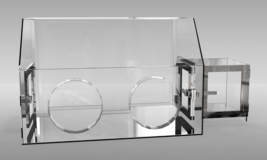
Glove Boxes and Air Lock Chambers
Standard Features and Options
- Control systems for maintaining stable environmental conditions
- Dual side access doors provide convenient through-put of materials and small process equipment
- Removable back panel allows large process equipment to be placed within the glove box
- Air lock chambers to isolate the glove box interior against ambient conditions when transferring materials
- Stainless steel frames that enhance sealing performance and protects the door plastic from damage, increasing overall life
- Changeable sleeve and glove combinations. Other glove types are also available
- Custom sizes and configurations available upon request
Glove Box and Air Lock Materials
- Acrylic (cast) – Ideal for general purpose processing. Provides some chemical resistance
- Polycarbonate – High impact resistance makes this material ideal for thermal stress applications. Provides good chemical resistance
- Polypropylene – Provides the best chemical resistance
- Non-Dissipative PVC – Provides excellent chemical resistance
- Static Dissipative PVC – Helps to reduce contamination build-up around and within the glove box by neutralizing static charges that attracts air borne particulate. Provides excellent chemical resistance
These hermetically sealed enclosures can be set-up as an ultra-clean, humidity controlled processing environment or used as a simple isolation chamber without filtered air and/or dry gas purging. When used with the optional Gas Purge™, Gas Monitor™b and Sonic Humidifier™ control systems, these glove boxes are transformed into an ideal contamination free, humidity controlled processing environment that is suitable for a variety of manufacturing and processing applications.
Relative Humidity Control Solutions
Relative Humidity Control:
For automated control over low R/H levels (0% to ambient RH) or for complete R/H control (0% – 100%), select the optional Gas Purge™, Gas Monitor™, and Sonic Humidifier™ control systems listed in the “Gas Control Solutions” section of this page. Click here for additional information.
|
|
|
Select the appropriate glove box with the appropriate quantity of 8” or 10” glove ports. Complete your glove box configuration by then selecting the air lock chamber(s), glove type, gas purge devices/controllers and other system options as needed to suite the application requirements.
| Plastic Glove Boxes – 8″ Diameter Glove Ports | |||||||||
|---|---|---|---|---|---|---|---|---|---|
| Type | Number of 8″ Glove Ports |
Glove Box Nominal Outside Dimensions W x D x H |
Acrylic* | Polycarbonate | Polypropylene** | Non-Dissipative PVC |
Static-Dissipative PVC*** |
Stainless Steel Shield |
Grounding |
| Part # | Part # | Part # | Part # | Part # | Part # | Part # | |||
| A | 2 | 30″ x 24″ x 23.5″ (762 x 610 x 570) |
GB1-2PS-A | GB1-2PS-C | GB1-2PS-P | GB1-2PS-N | GB1-2PS-D | GBS-2PS | GB-SG1 |
| 35″ x 24″ x 23.5″ (889 x 610 x 570) |
GB1-2PL-A | GB1-2PL-C | GB1-2PL-P | GB1-2PL-N | GB1-2PL-D | GBS-2PL | |||
| B | 4 | 59″ x 24″ x 23.5″ (1499 x 610 x 570) |
GB1-4PS-A | GB1-4PS-C | GB1-4PS-P | GB1-4PS-N | GB1-4PS-D | GBS-4PS | |
| 65″ x 24″ x 23.5″ (1676 x 610 x 570) |
GB1-4PL-A | GB1-4PL-C | GB1-4PL-P | GB1-4PL-N | GB1-4PL-D | GBS-2PL | |||
| Plastic Glove Boxes – 10″ Diameter Glove Ports | |||||||||
|---|---|---|---|---|---|---|---|---|---|
| Type | Number of 10″ Glove Ports |
Glove Box Nominal Outside Dimensions W x D x H |
Acrylic* | Polycarbonate | Polypropylene** | Non-Dissipative PVC |
Static-Dissipative PVC*** |
Stainless Steel Shield |
Grounding |
| Part # | Part # | Part # | Part # | Part # | Part # | Part # | |||
| A | 2 | 30″ x 24″ x 23.5″ (762 x 610 x 570) |
GB2-2PS-A | GB2-2PS-C | GB2-2PS-P | GB2-2PS-N | GB2-2PS-D | GB-SD-2PS | GB-SG1 |
| 35″ x 24″ x 23.5″ (889 x 610 x 570) |
GB2-2PL-A | GB2-2PL-C | GB2-2PL-P | GB2-2PL-N | GB2-2PL-D | GB-SD-2PL | |||
| B | 4 | 59″ x 24″ x 23.5″ (1499 x 610 x 570) |
GB2-4PS-A | GB2-4PS-C | GB2-4PS-P | GB2-4PS-N | GB2-4PS-D | GB-SD-4PS | |
| 65″ x 24″ x 23.5″ (1651 x 610 x 570) |
GB2-4PL-A | GB2-4PL-C | GB2-4PL-P | GB2-4PL-N | GB2-4PL-D | GB-SD-4PL | |||
* Acrylic is susceptible to damage with the prolonged use of alcohol and other cleaning/disinfecting agents. Equipment fabricated out of Static Dissipative PVC may be a better choice in these instances.
** Polypropylene glove boxes feature a non-dissipative PVC viewing window and a 120V fluorescent light fixture (add -220 to the end of the part number for 220V light fixture).
*** It is highly recommended that stainless steel shields be installed in Static Dissipative PVC desiccators to protect the chamber bottom surface from repeated scraping and rubbing, which can lead to loss of dissipative properties.
Additional product information:
- Fully gasketed removable back panel allows larger equipment to be placed within the glove box
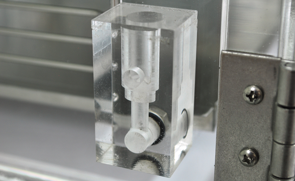
- Features a right side access door (standard) and an optional left side access door. Access doors features stainless steel hinges & door frame, a triple chromed compression lift latch & catch and a one-piece gasket.
- Glove boxes include drilled and tapped ports (1/8” NPT) for gas purge fittings and installation of an Auto-Adjust RB™ Valve (sold separately).
- Stainless steel shields prevent scratching and un-necessary damage to the glove box.
- Grounding interconnects the stainless steel shield, door-latch, door frame /hinges with conductive tape, all of which is terminated at a multi-lug grounding block. A ground fault circuit interrupter should be considered to provide personnel protection
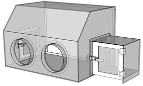
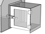
| Front Load Air Lock
|
Front load air locks allow materials to be loaded from the front side, where side access may not be available. Interior door swings inward towards the back and the exterior door swings outward away from the glove box |
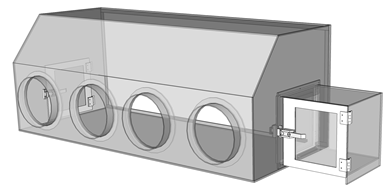
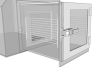
| Pass-Through Air Lock
|
Pass-through air locks feature in-line doors and chrome plated racks that accommodate optional shelving for organized transfer of materials. Interior door swings inward towards the back and the exterior door swings. |
| Air Lock Chamber for Plastic Glove Boxes | |||||||||||
|---|---|---|---|---|---|---|---|---|---|---|---|
| Type | Mounting side of glove box |
Air Lock Nominal Outside Dimensions W x D x H |
Acrylic* | Polycarbonate | Polypropylene** | Non Dissipative PVC |
Static Dissipative PVC*** |
Shelf Acrylic |
Shelf Stainless Steel, Non-Perforated |
Stainless Steel Shield |
Grounding |
| Part # | Part # | Part # | Part # | Part # | Part # | Part # | Part # | Part # | |||
| A | Right Hand | 11.75″ x 10″ x 10″ (298 x 254 x 254) |
GBA-R1A | GBA-R1C | GBA -R1P | GBA -R1N | GBA -R1D | ——- | ——- | GBA -SD1 | GBA -G1 |
| Left Hand | GBA-L1A | GBA-L1C | GBA -L1P | GBA -L1N | GBA -L1D | ||||||
| B | Right Hand | 11.75″ x 9.75″ x 10″ (298 x 248 x 254) |
GBA-R2A | GBA -R2C | GBA -R2P | GBA -R2N | GBA -R2D | D112-ASF | D112-SF | GBA -G2 | |
| Left Hand | GBA-L2A | GBA -L2C | GBA -L2P | GBA -L2N | GBA -L2D | ||||||
* Acrylic is susceptible to damage with the prolonged use of alcohol and other cleaning/disinfecting agents. Glove boxes made of Static Dissipative PVC may be a better choice in these instances.
** Polypropylene air locks feature a non-dissipative PVC viewing window.
*** It is highly recommended that a stainless steel shield be installed in Static Dissipative PVC air locks to protect the work surface from repeated scraping and rubbing, which can lead to loss of dissipative properties.
- Air Locks include drilled and tapped ports for gas purge fittings and installation of an Auto-Adjust RB™ Valve (sold separately)
- Nominal outside dimensions do not include the access door, door catch, hinges or miscellaneous fasteners
- Grounding interconnects the air locks door-latch, door frame/hinges and stainless steel shield (if purchased) with conductive tape and final termination with the glove box grounding. Air lock grounding requires the glove box to feature grounding
- Acrylic shelves should not be used with static-dissipative PVC glove box and air lock combinations.
Bonded Sleeve and Glove Combination
Economical and durable, this combination features gloves that are permanently vulcanized to the sleeves, which are made of heavy-duty, chemical-resistant neoprene and designed to be used on 8” (203 mm) or 10” (254 mm) diameter glove ports. Gloves are also made of neoprene. Clamps included.
 |
|
|||||||||||||||||
Changeable Sleeve and Glove Combination
Flexible by design, these accordion sleeves can be used with a variety of gloves, allowing glove sizes and types to be changed without changing the sleeve. The convoluted design provides the operator with more comfort and better air circulation around the arms. Designed to be used with either 8” (203 mm) or 10” (254 mm) diameter glove ports. Clamps included.
 |
|
|||||||||||||||||
Four Outlet Power Strip:
- Provides an convenient electrical connection for process equipment being used within the clean processing environment
- Mounted horizontally on the inside rear wall 3” from the bottom work surface
- Includes a master on/off switch, 4-outlets and a 15-amp circuit breaker
| Four Outlet Power Strip |
|---|
| Part # |
| LF-PS-4 |
Gas Control Solutions
Flow Meters
- Scales are hot stamped into the front of the acrylic body and will not wear off
- Bodies are precision cut and machined from clear acrylic blocks with a smooth tapered bore that provides perfect visibility of the indicating float
- Accuracy is ±5% of full scale with a scale average 2″ long
- Features brass (stainless steel optional) inlet and outlet connections, black glass float, Buna-N O-rings and tapped for 1/8″ NPT female process connection (vertical mounting)
- Service: Compatible gases and liquids
- Includes nickel plated brass hex nipple and 90 degree elbow (female x male), 1/8” (3.18mm) pipe size for connection to Cleanroom Synergy desiccators, glove boxes or other gas purged enclosures
| Flow Meter (fittings included) | ||
|---|---|---|
| ,6 – 5 SCFH | 1 – 10 SCFH | 2 – 20 SCFH |
| Part # | Part # | Part # |
| CCE-FME | CCE-FMH | CCE-FMK |
Auto-Adjust™ RB Valve
- Automatically adjusts to gas flow rates and possible sudden surges
- Eliminates possible negative pressure incidents due to its one way air flow design
- Continuously bleeds off excess internal gas to maintain a safe pressure within desiccators, glove boxes and other hermetically sealed enclosures
- Includes a nickel plated brass hex nipple fitting (1/8” NPT) with a polyurethane O-ring to ensure a positive seal against the hermitically sealed enclosure
- One Auto R/B Valve per cabinet is required if desiccator is to be purged with dry gas
- Installation of one Auto-Adjust™ RB Valve in each desiccator storage chamber eliminates cross contamination and R/H fluctuation in the unopened chambers
| Auto-Adjust™ RB Valve |
|---|
| Part # |
| CCE-PRV |
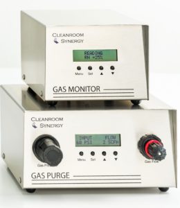
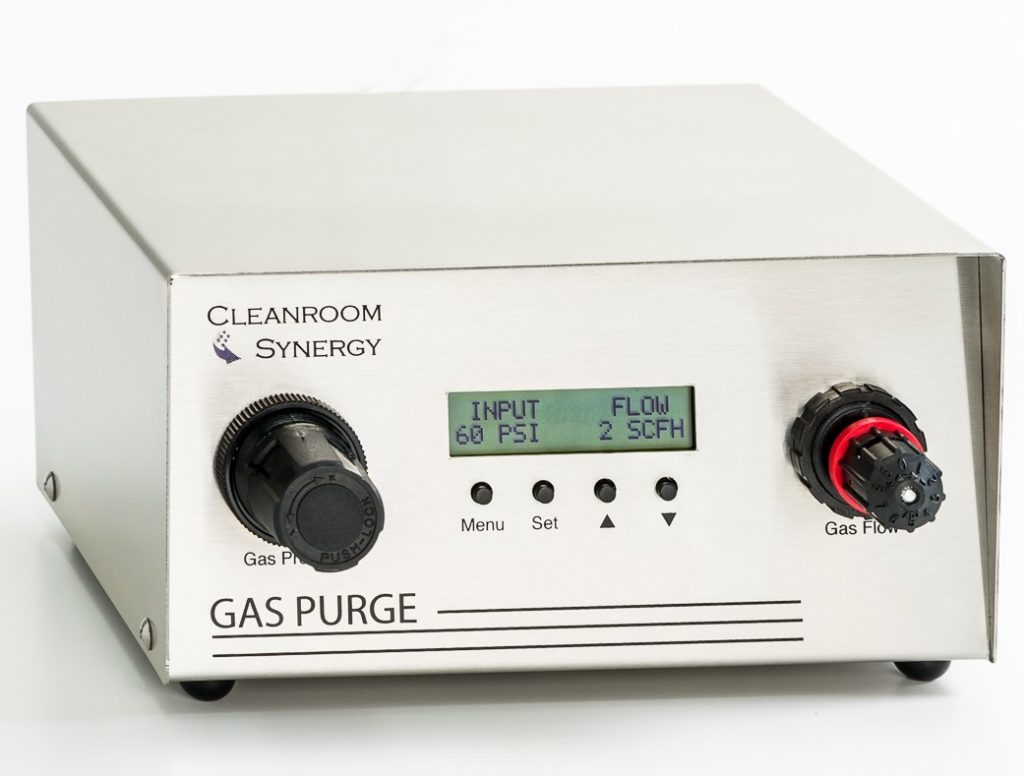
Gas Purge™ Control System
- Automatically activates a high-flow gas purge when a chamber door is accessed
- Protects moisture sensitive materials against oxidation, increasing product yield
- Ensures a constant positive pressure within glove boxes and other hermetically sealed enclosures to block out contamination influx
- Dramatically reduces purge gas cost when compared to systems using only a mechanical flow meter
- Adjustable electronic flow meter precisely regulates the flow rate of the purge gas
- Digital pressure regulator safely adjusts the pressure of the incoming gas
- Operates in conjunction with the optional Gas Monitor™ Control Unit to maintain desired sub-ambient moisture level (down to 0% RH)
- High-reliability door switches are rated for millions of operations. One per desiccator chamber required
- Works with120/240VAC, 50/60Hz, and requires no manual power selection
The Gas Purge™ Controller monitors and regulates the dry gas that will flow into the desiccator when it is needed to lower the R/H or when a chamber door is opened. It has a gas regulator to control the pressure of the incoming gas and electronic flow meter that regulates and maintains the low flow of gas. Also provides audible/visual warnings when the supply gas is getting low, a desiccator door has been left opened or if the R/H set point has not been reached.
| Gas Purge™ Controller |
Sensor Switch |
|---|---|
| Part # | Part # |
| GPC-D1 | GPC-D1S |
One sensor switch required per desiccator chamber
Gas Monitor™ Control System
- The Gas Monitor™, when used in conjunction with the Gas Purge™ Controller will automatically maintain desiccator R/H levels from ambient down to R/H of the purge gas (0% for most dry gases)
- Incorporates a state of the art micro-controller, a bright readable R/H display and simple control buttons
- Since the desiccator only needs gas when the R/H rises above the set point, it uses much less gas resulting in large cost savings
- Small solid state humidity sensor never needs calibration, easily installed and takes a small amount of desiccator space
- Can be used to monitor R/H levels in any enclosure without the use of the Gas Purge™ controller
- Works with120/240VAC, 50/60Hz, and requires no manual power selection
The Gas Monitor™ controller measures the R/H of the chamber which contains the Gas Sensor. It has provisions to enter a desired R/H set point and will issue a command to the Gas Purge™ controller to lower the desiccator cabinet’s humidity level whenever it senses a reading above the R/H set point. It also monitors the open and closed positions of the desiccator doors and issues a command to the Gas Purge™ controller to introduce dry gas at a high flow rate while the door is opened and for a preset time after the door is closed (factory set at 60 seconds).
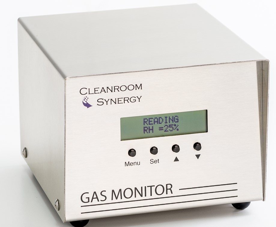
| Gas Monitor™ Controller |
Gas Monitor™ Sensor |
|---|---|
| Part # | Part # |
| GMC-1 | GMC-1S |
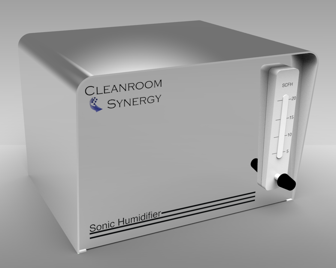
Sonic Humidifier™
- Provides a stream of high humidity gas to enclosures that require higher then ambient R/H level
- Automatically generates moisture using a sonic transducer and a connected water source
- Can be used for environmental testing of a large variety of devices to determine performance in wet conditions
- Works in conjunction with the Gas Purge™ and Gas Monitor™ control systems to maintain a specific R/H set point
- Works with120/240VAC, 50/60Hz, and requires no manual power selection
For actual control of the humidity level, the Sonic Humidifier™ must be used in conjunction with the Gas Purge™ and Gas Monitor™ control systems.
|